Magnets and magnetic field

Key questions

  • Why are some objects magnetic?
  • What is the magnetic field of a permanent magnet like? What is the magnetic field of Earth like?
  • How is the direction of the magnetic field of a current-carrying conductor determined?
  • What factors affect the strength of the magnetic flux density around a current-carrying conductor?

The magnetism of objects and materials

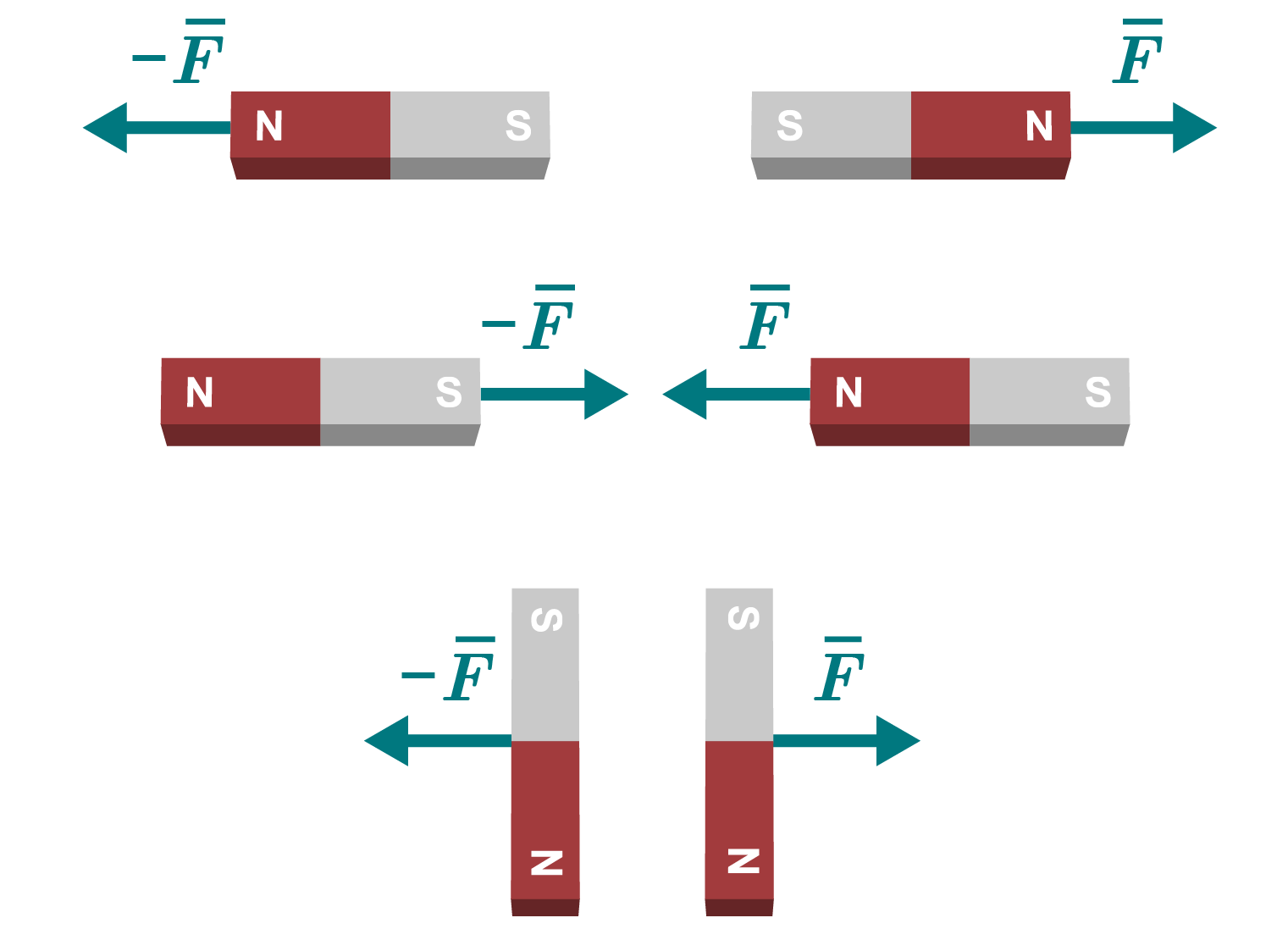
Illustrations of three different bar magnet situations with force arrows. In situation 1, the south poles of the magnets face each other, resulting in equal force lines in opposite directions. In situation 2, the south and north poles of the two magnets are facing, resulting in attractive forces that are drawn towards the same points. In situation 3, the sides of the two magnets are parallel, resulting in equal force lines away from each other.

Magnets interact by either attracting or repelling each other. Each magnet has two types of poles: the north and south poles, abbreviated as N and S. Like poles repel one another, while opposite poles attract one another.

A compass needle is a sensitive magnet. When the compass is brought near a magnetic object or a current-carrying conductor, a magnetic interaction acts on the compass needle, causing it to turn. The north pole of the magnet attracts the south pole of the compass needle, and vice versa. A force acts on the north pole of the compass needle, aligning it with the direction of the magnetic field. From the movement of the compass needle, it can also be inferred that the interaction weakens as the distance from the magnet increases. The video below demonstrates the direction of the magnetic field around a bar magnet.

[embedded content beginning]
[embedded content end]

The strength of a magnetic field is represented by the quantity magnetic flux density. Its symbol is B​ and its unit is the tesla (T​). Magnetic flux density has a direction, making it a vector quantity.

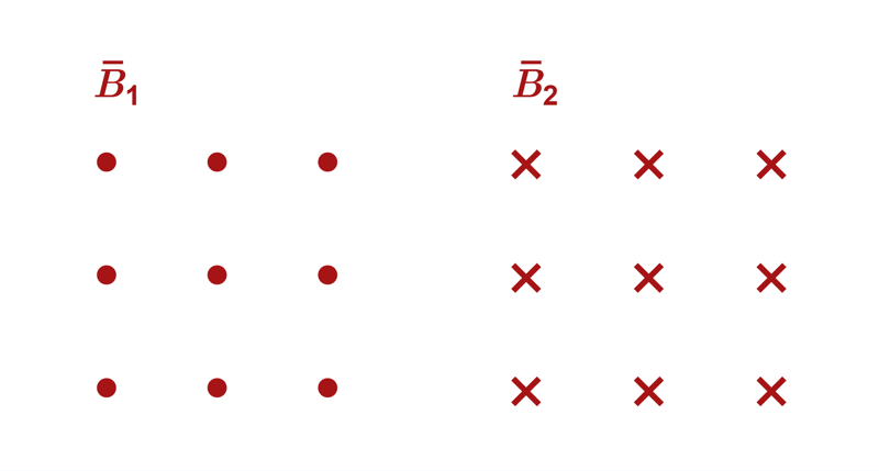
In the context of magnetic interactions, vector quantities are often represented in three dimensions. For example, magnetic flux density is depicted using symbols that indicate its direction either coming out of the drawing (⋅, dot) or going into the drawing (×, cross). Similar symbols can also be used for other vector quantities. In the image, the magnetic field on the left points out of the plane, while the magnetic field on the right points into the plane. The magnetic fields are homogeneous, as the dots and crosses are spaced evenly from one another.

Illustration of two magnetic fields: B1 (dots) and B2 (crosses).

Magnets attract not only other magnets but also objects made of certain materials, particularly iron. In the interaction between iron and a magnet, the iron becomes magnetised as the external magnetic field surrounding the iron object causes it to become magnetic. This effect can persist for a period of time. Permanent magnetisation, or a permanent magnet, can be achieved, for example, by exposing iron to an external magnetic field while cooling it from a high temperature.

The magnetic properties of an object are based on its structure. These include the motion of electrically charged particles and a property of elementary particles called spin. In magnetic objects, the atoms of the material group into magnetic domains, which, in non-magnetic objects, are arranged randomly, canceling out each other's effects. When the material becomes magnetised, the domains align in the same direction, making the entire object magnetic. Most materials do not become magnetised. For example, the molecular structure of wood does not allow for magnetic alignment.

Photograph of a digger equipped with a magnet lifting heavy construction debris in a city.
[embedded content beginning]
[embedded content end]

Iron is an example of a ferromagnetic material. In addition to iron, ferromagnetic materials include cobalt, nickel, and a few of their alloys and compounds. Ferromagnetic materials strengthen an external magnetic field and become strongly magnetised. The magnets we are familiar with from everyday life are made of ferromagnetic materials. In contrast, the magnetisation of paramagnetic or diamagnetic materials is significantly weaker. Paramagnetic materials slightly enhance the external magnetic field, creating a weak attractive interaction. Diamagnetic materials weaken the magnetic field, and the interaction is repulsive.
The magnetic field of a permanent magnet

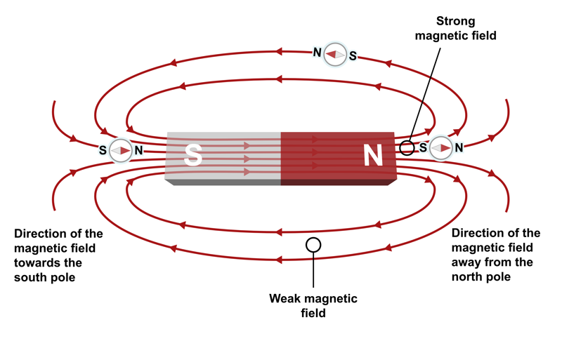
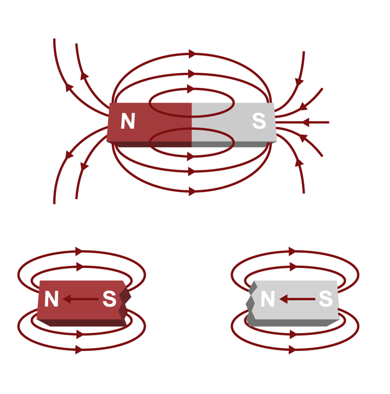
Magnetic interaction is modelled using a field, in the same way as gravitational interaction (Resonance 5) or electric interaction. A magnetic field is represented using a field line diagram. The field lines are closed curves that, outside the permanent magnet, lead from the north pole to the south pole of the magnet. The density of the field lines indicates the strength of the magnetic field at a given location. Below is an image of the magnetic field generated by a bar magnet.

An illustration of a bar magnet's magnetic field. The field line arrows go from the north pole to the south pole, showing the direction of the field. Weak magnetic fields are shown at the sides of the bar magnet, while strong magnetic fields are seen near the poles.

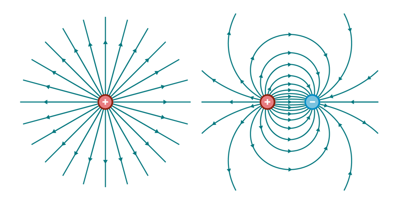
For comparison, below are field line diagrams for the electric field of a positive point charge and an electric dipole. The field lines of a single point charge extend to infinity and do not form closed loops. The electric field lines between two opposite charges go from the positive charge to the negative charge. The dipole electric field is somewhat similar to the magnetic field of a bar magnet, but the key difference is that the field lines of a magnetic field are continuous and form a closed loop.

Illustrations of the electric fields of a single positive particle (straight lines emanating from the particle) and a positive and negative particle (curved lines travelling between the two poles).

The field of a bar magnet is not constant; it varies depending on distance and location. The field of a bar magnet is inhomogeneous. Below is a simulation where you can observe the direction and magnitude of magnetic flux density around a bar magnet.

[embedded content beginning]
[embedded content end]
Simulation of the direction and strength of magnetic flux density
Accessibility description​

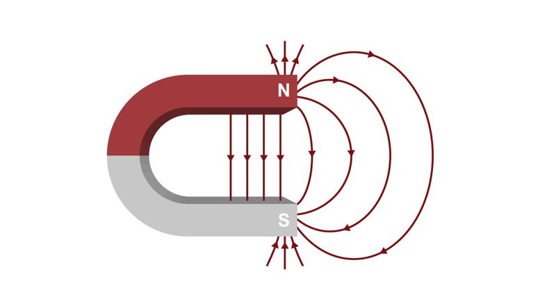
Another common type of permanent magnet is the horseshoe magnet. In a horseshoe magnet, the north and south poles face each other. Its magnetic field is strongest between these opposing poles. In the image below, the field lines are not drawn to continue within the magnet itself.

Illustration of the magnetic field of a horseshoe magnet.

The Earth's magnetic field

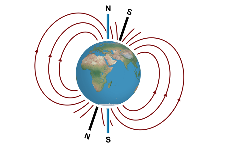
The compass has been used for navigation since before the beginning of the Common Era. A compass indicates the direction of the Earth's magnetic field. The needle of the compass points towards the Earth's magnetic south pole, which is located near the geographic North Pole. However, significant deviations in the shape of Earth’s magnetic field are caused by the composition of the Earth's crust and solar wind. Geological studies have shown that the Earth's magnetic field has varied throughout history.

Illustration of the magnetic field of the planet Earth. The magnetic south pole is near the geographic north pole and vice versa. Field lines travel from the magnetic north pole to the magnetic south pole.

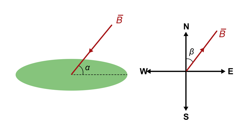
The Earth's magnetic field can be simplified to resemble the magnetic field of a bar magnet. At the equator, the field is approximately parallel to the Earth's surface. Close to the North Pole, the field points towards the ground, as the magnetic south pole is located beneath the Earth's surface. The angle between the Earth's surface and the magnetic field is called inclination. The angle of inclination is marked in the adjacent image with the symbol α.

Since the Earth's magnetic field does not perfectly resemble that of an ideal bar magnet, the direction of the field varies locally. Declination refers to the angle between the local direction of the magnetic field and the direction towards geographic poles. The angle of declination is typically a few degrees, but it can also be much more, especially at high latitudes. The declination is marked in the image with the symbol β.

Two illustrations showing the angles of inclination and declination.

The magnetic field of a current-carrying conductor

In addition to permanent magnets, an electric current also generates a magnetic field. The first observations of a magnetic field produced by an electric current were made by the Danish physicist Hans Christian Ørsted in 1820. His observations provided the foundation for the modern theory of electromagnetism, in which electrical and magnetic phenomena are regarded as manifestations of the same fundamental interaction.

A stationary (static) electric charge does not create a magnetic field around it. However, a moving charged particle, for example in an electric current in a conductor, generates a magnetic field. In the accompanying video, the magnetic field near a cable is observed using a compass.

[embedded content beginning]
[embedded content end]
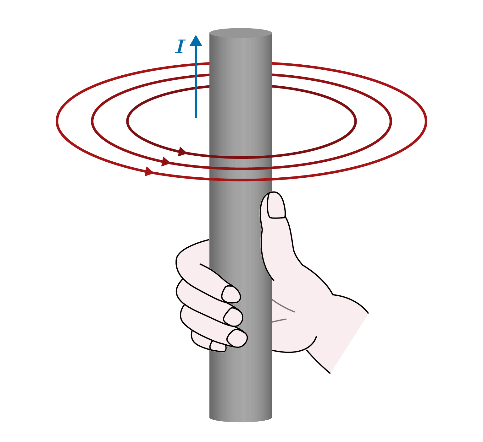
An illustration of the right-hand rule. When the thumb is pointing upwards, the electric current also travels upwards and the electric field is perpendicular and counterclockwise.
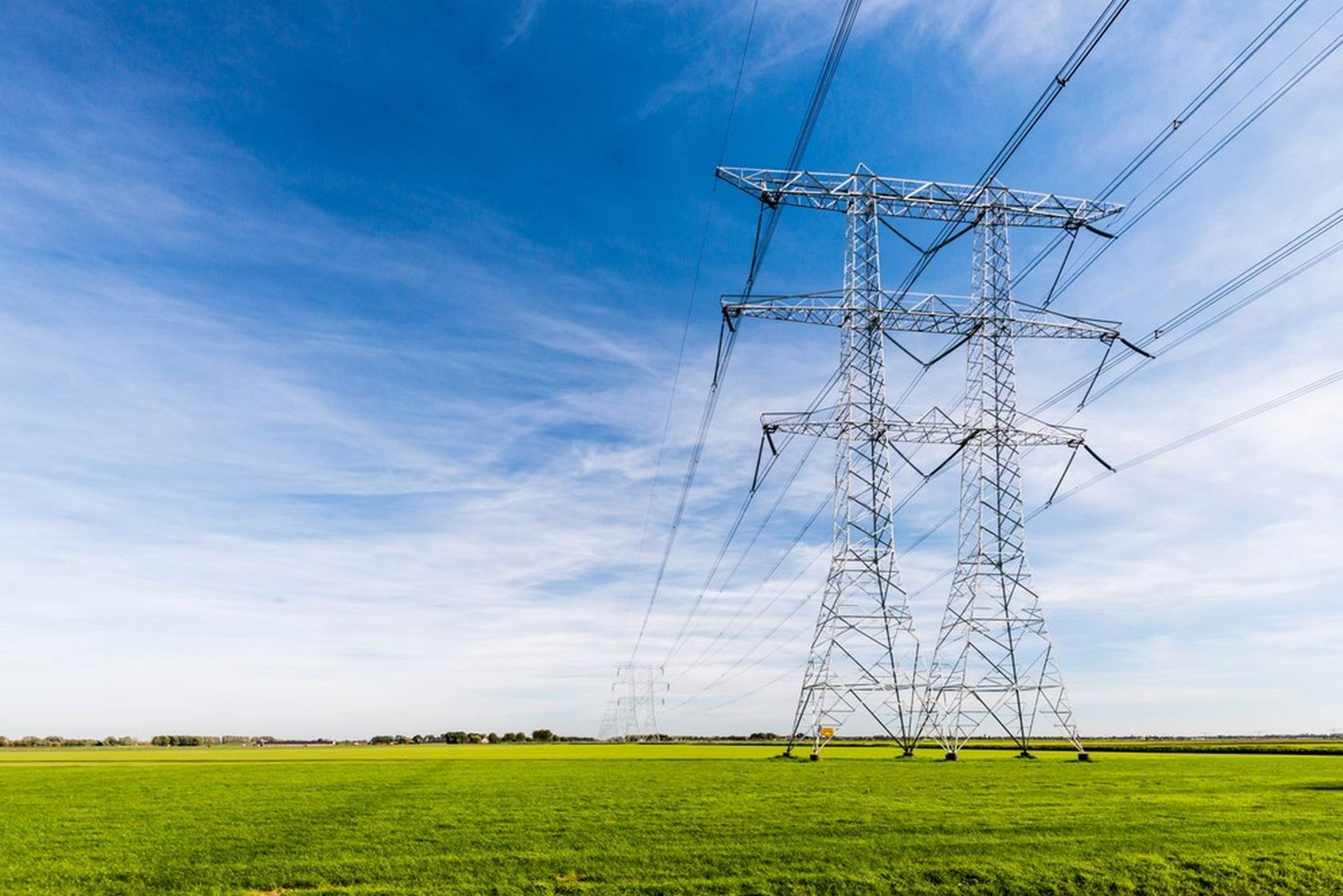
Photograph of high-tension power lines in a field.

In the video, it was observed that the magnetic field of a current-carrying conductor points in opposite directions on different sides of the conductor. The field lines form ring-like patterns around the conductor. Farther from the conductor, the compass responds more weakly to the electric current, so the field seems to weaken as one moves away from the conductor. The direction of the conductor’s field can be determined using the right-hand rule: when the thumb indicates the direction of the electric current, the curling of the fingers indicates the direction of the magnetic field.

The strength of the magnetic field of a current-carrying conductor is influenced by the magnitude of the electric current and the distance from the conductor. Precise measurements reveal a direct proportionality between the magnetic flux density and the electric current, B I . In turn, there is an inverse relationship between distance and magnetic flux density ( B 1 / r). These relationships apply when the conductor extends far in both directions from the point of observation. The model provides accurate predictions for long current-carrying conductors.

In school experiments or in everyday life, the magnetic fields created by electric currents are fairly weak. Even though power transmission lines carry large electric currents, the magnetic flux density they produce at ground level is typically weaker than the Earth’s magnetic field. This is due to the inverse dependence on distance.

The magnetic field also depends on the medium in which the conductor is located. The ability of different media to transmit magnetic interaction is measured by a quantity called permeability, denoted by the symbol μ.​ The permeability of a vacuum, which is a fundamental constant, is denoted by μ 0 ,​ and its value is  μ 0 = 4 π 10 7 T m A ​​. Air does not affect the magnetic field significantly differently from a vacuum, so situations where the medium is air are modelled using the vacuum permeability.

The magnetic field of a current-carrying conductor

A current-carrying conductor generates a magnetic field around it. The field lines form circular loops around the conductor. The direction of the field can be determined using the right-hand rule.

The magnetic flux density at a certain point near a long straight conductor depends on the electric current in the conductor ( I ) and on how far the point is from the conductor ( r ).

B = μ 0 2 π I r

μ 0 ​ is the vacuum permeability, whose value is  μ 0 = 4 π 10 7 T m A .

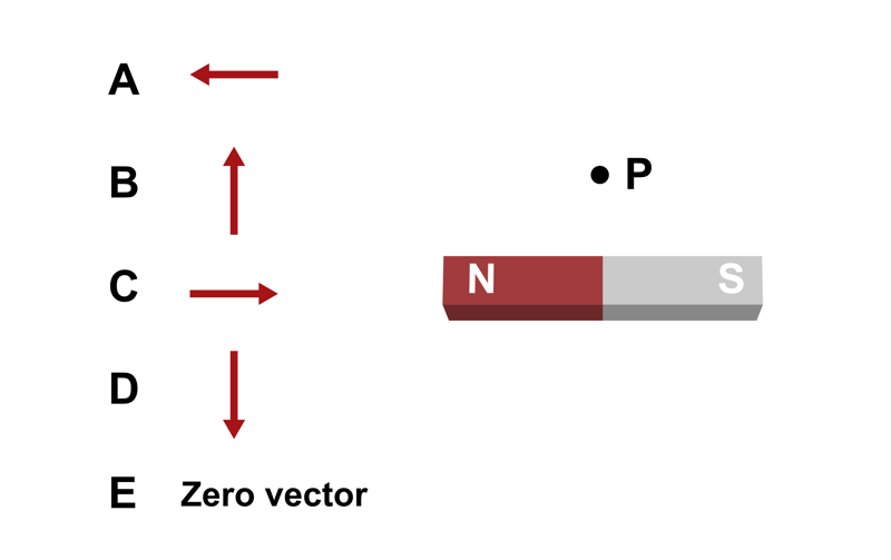
1. Which of the following vectors best represents the magnetic flux density at point P?

  • A
  • B
  • C
  • D
  • E
Illustration of a horizontal bar magnet with its north pole to the right and point P above the centre of the bar magnet. There are four possible arrows: A (left), B (up), C (right), D (down) and E: zero vector.

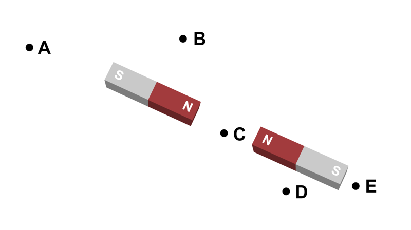
2. Which point in the figure has the smallest magnetic flux density?

  • A
  • B
  • C
  • D
  • E
A illustration of two bar magnets in a line with their north poles facing each other, with points A (to the left of the left magnet), B (above the left magnet), C (between the magnets), D (below the right manget) and E (to the right of the right magnet).

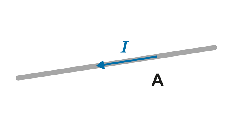
3. The electric current is oriented in a wire as shown in the figure. What is the direction of the magnetic flux density at point A, which is directly below the wire?

  • Towards the wire.
  • Away from the wire.
  • Out of the page.
  • Into the page.
A slanted conductor with current to the left and down. Point A is below the conductor.

Compass and navigation

On the Earth’s surface, the local direction of the magnetic field almost always differs more or less from the geographical north–south direction. This difference is called declination. It must be taken into account when navigating so that the compass’s north direction corresponds to that of the map. Declination, also known as variation, is marked on most maps, which allows the compass scale to be adjusted accordingly.

Inclination, meaning the deviation of the magnetic field from the horizontal, also affects how the compass functions. With a compass, we aim to observe the horizontal component of the Earth’s magnetic field, so the needle is balanced to account for inclination. Inclination varies with latitude, which is why compass manufacturers produce different versions of compasses. Using a compass in the wrong region causes the needle to tilt vertically and introduces extra friction, preventing it from rotating smoothly.

Relative permeability

Relative permeability  μ r is a factor that represents the effect of the medium on magnetic phenomena. The relative permeability is calculated as the ratio of the permeability μ to the vacuum permeability  μ 0 .

μ r = μ μ 0

For example, the relative permeability of iron is 200 000 and the relative permeability of air is 1.000 000 37.

Do magnetic monopoles exist?

When a bar magnet is cut into pieces, each piece becomes a new magnet. Therefore, cutting a bar magnet does not produce isolated magnetic poles or magnetic monopoles. Instead, each smaller magnet will have its own north and south poles.

According to our current understanding, isolated magnetic poles do not exist. Although modern theories do not completely rule out their existence, magnetic monopoles have never been observed experimentally.

An illustration of the electric field of a bar magnet and the electric fields of two parts of the magnet when they are detached. When the magnet is split in half, new south and north poles are formed.

Examples

Example 1

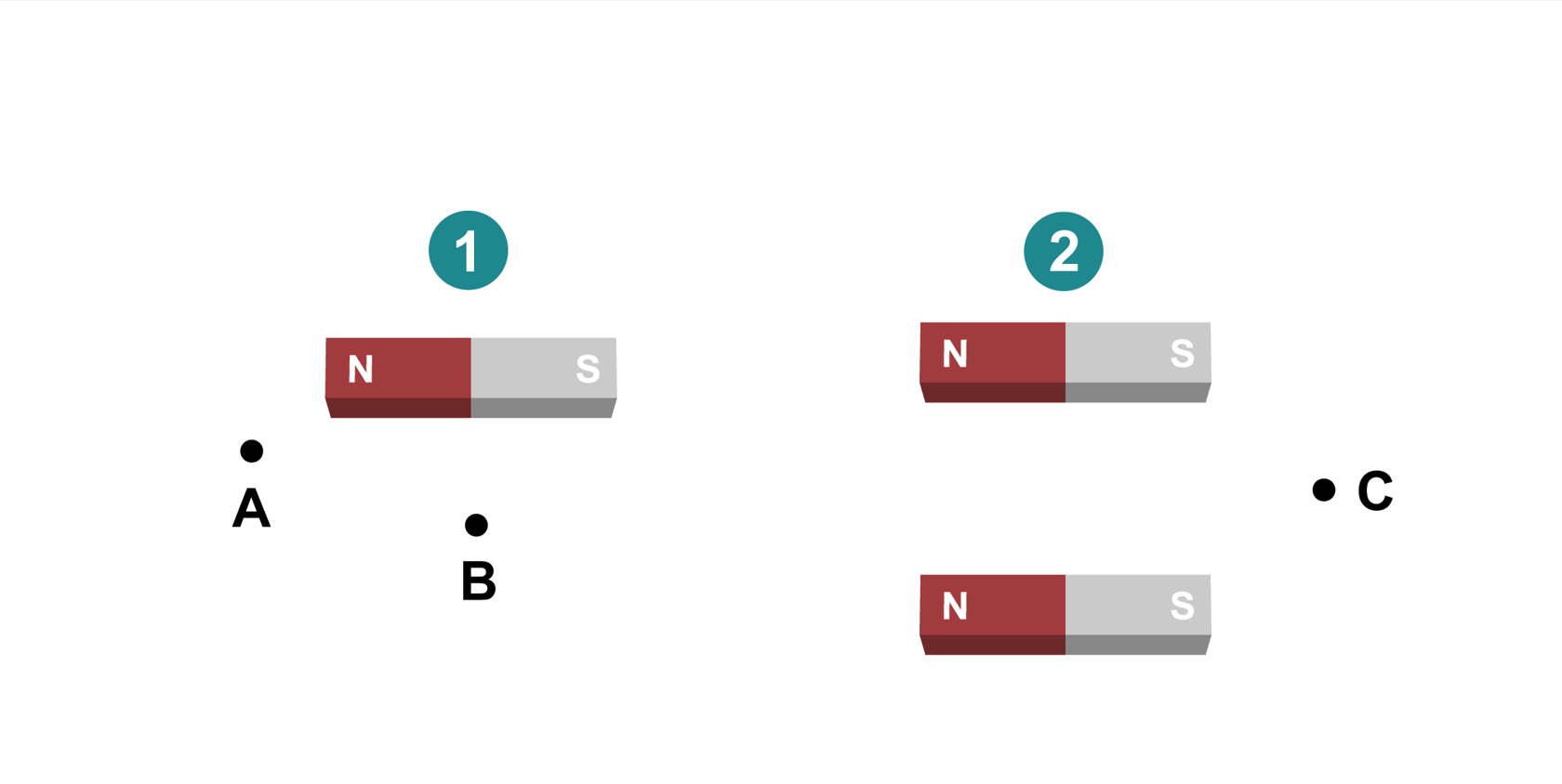
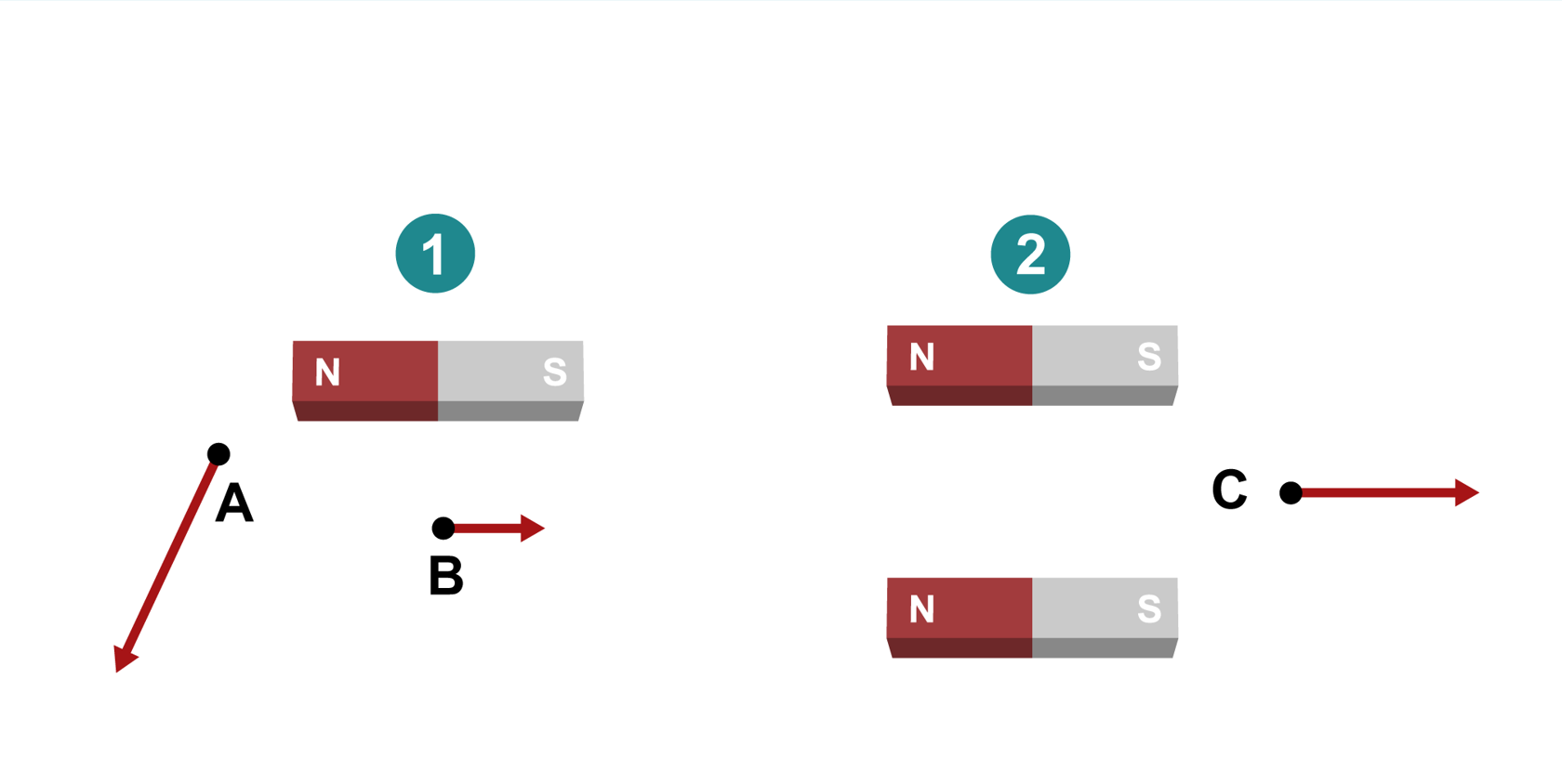
Figures 1 and 2. Figure 1 shows a horizontal bar magnet (north pole on the left), with point A below and to the left of the magnet and point B below the centre of the magnet. Figure 2 shows two parallel bar magnets (north poles to the left), with point C between and to the right of the two magnets.

Copy the figures 1 and 2 (below) into your notebook and sketch the magnetic flux density vectors at the marked points A–C. 

Pay attention to the directions and magnitudes of the magnetic flux density vectors.

Example 1 solution

Figures 1 and 2. Figure 1 shows a horizontal bar magnet (north pole on the left), with point A below and to the left of the magnet and point B below the centre of the magnet.  An arrow is drawn down and to the left for point A, while a shorter arrow is drawn to the right for point B. Figure 2 shows two parallel bar magnets (north poles to the left), with point C between and to the right of the two magnets. A long arrow to the right is drawn for point C.

Example 2

There is an electric current of 6.7 amperes in a straight conductor. How far from the conductor is its magnetic field weaker than the Earth's magnetic field? The magnetic flux density of the Earth's magnetic field is approximately 55 μT.

Example 2 solution

The magnetic flux density around a long straight conductor can be calculated as

B = μ 0 2 π I r

From this, the expression for distance can be solved as

r = μ 0 2 π I B

r = 4 π 10 7 T m A 2 π 6 . 7  A 55 10 6 μ  T = 0.024 3 m 0.024  m

At a distance greater than 2.4 cm from the conductor, its magnetic field is weaker than the Earth's magnetic field.

Pause and reflect

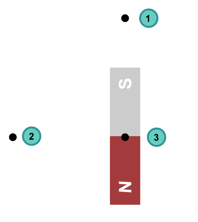
1. What is the direction of the magnetic field at point 1 near the bar magnet?

  • Up
  • Down
  • Right
  • Left
  • The field is approximately zero
Illustration of a vertical bar magnet (south pole pointed up) with points marked in the drawing: point 1 is above the south pole, point 2 to the right of the magnet's centre and point 3 on the magnet's centre.

2. What is the direction of the magnetic field at point 2 near the bar magnet?

  • Up
  • Down
  • Right
  • Left
  • The field is approximately zero

3. What is the direction of the magnetic field at point 3 inside the bar magnet?

  • Up
  • Down
  • Right
  • Left
  • The field is approximately zero

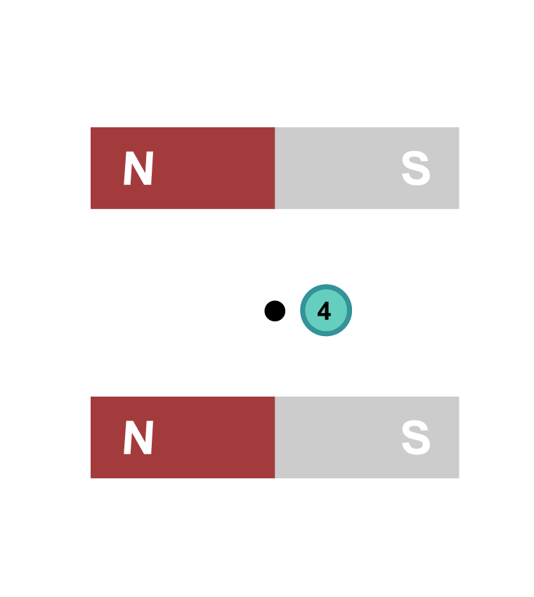
4. What is the direction of the magnetic field at point 4 near two identical bar magnets?

  • Up
  • Down
  • Right
  • Left
  • The field is approximately zero
Illustration of two parallel horizontal bar magnets (north poles to the left) one above the other with a point between them.

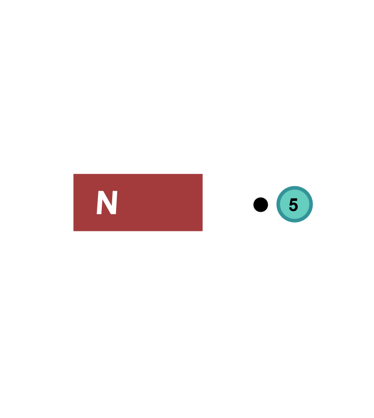
5. A bar magnet is cut in the middle, and the half containing the original south pole is removed. What is the direction of the magnetic field at point 5?

  • Up
  • Down
  • Right
  • Left
  • The field is approximately zero
Illustration of the red (north) half of a bar magnet with point 5 to its right.