Key questions
- In which situations does an object rotate?
- How do you determine the moment of a force?
- How does the magnitude of a force affect the moment of force?
You can use a wrench to loosen the bolt on a car wheel. A torque is exerted on the bolt, which loosens the bolt. The long shaft of the wrench increases the torque, so you do not need that much force to loosen the bolt.
The force does not move the bolt but instead the torque causes the bolt to rotate, i.e. change its orientation. The quantity for the turning effect of a force is the moment of force (often abbreviated just as the moment, also known as torque). In Resonance 4, we studied situations where the forces either had no torque or the torque was insignificant. The torque is accounted for in situations where an object can rotate and the rotation is of interest to us.
The torque is emphasised when the force acts on an object asymmetrically. If a force acts evenly on the surface of an object, there is no torque. This is the case when drag acts on the entire lower part of a flying tennis ball, for example. The force attempts to move each point on the object, which makes the ball fall in the same position. If a force acts only on the upper corner of an object instead, the force creates torque and can tip or turn the object over.

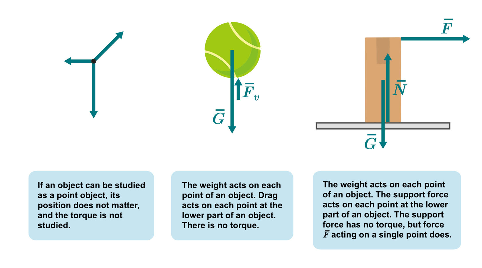

An object is difficult to keep balanced with a support force that is only acting on a single point. When you use an object like a pencil, you grab it from several points to increase the number of support points.
Still, balancing an object with only one support force is possible. You have probably played with a pencil, trying to keep it balanced on one finger. Even nature sometimes creates strangely balanced structures.
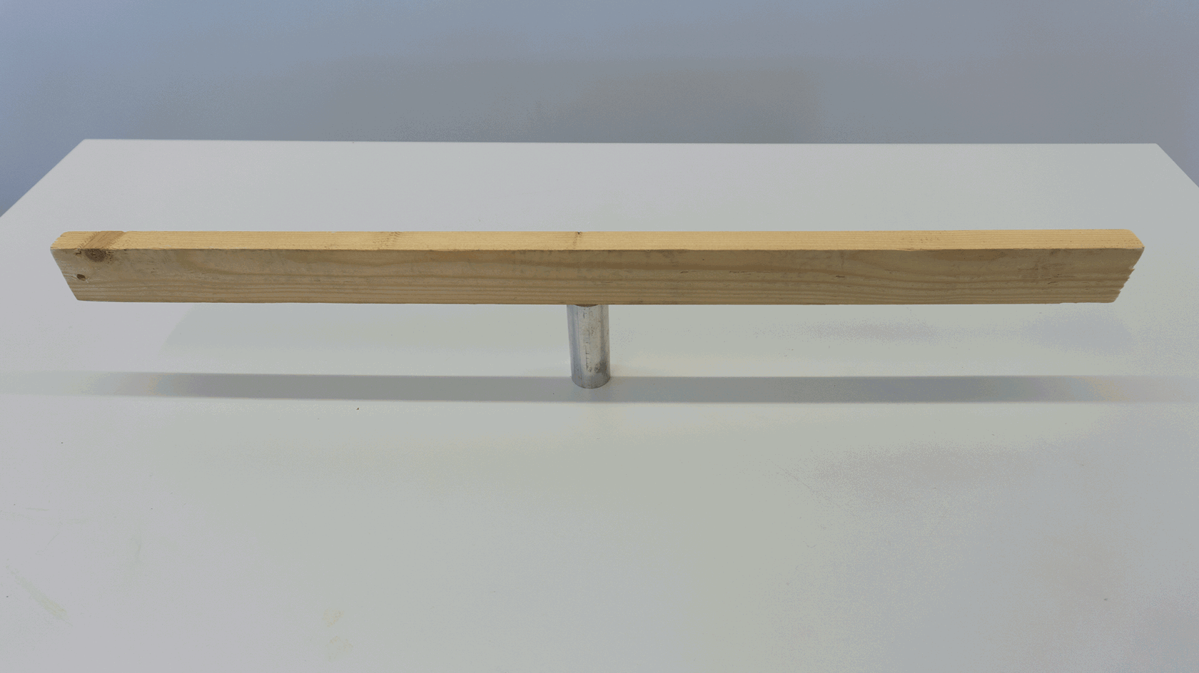
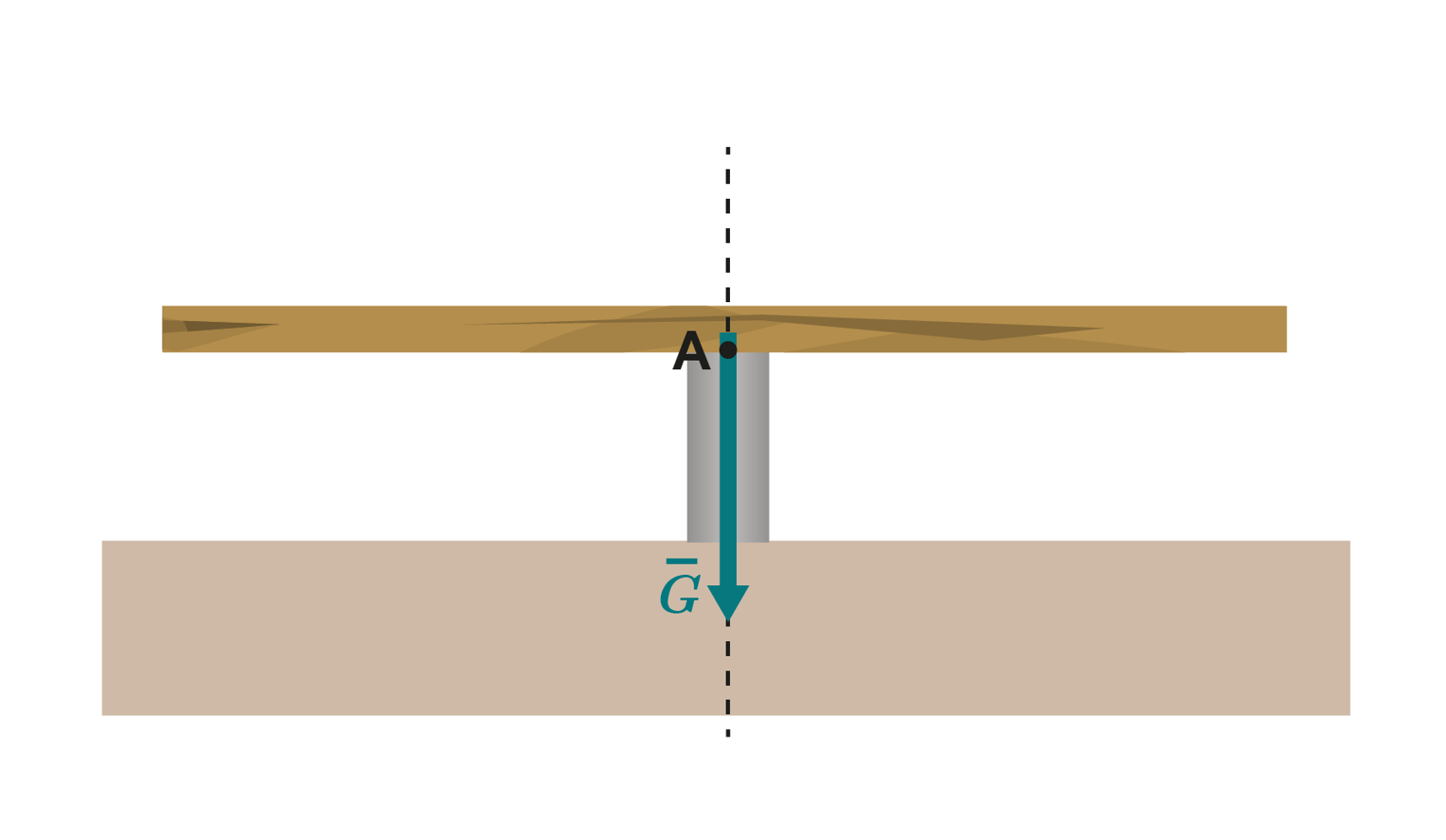
A single fulcrum will keep an object balanced only if a line of action of gravity passes through the supported area. In these situations, the support force and weight do not have torques. The wooden bar in the image below stays balanced, because the direction of action of the weight (marked with a dotted line) passes through fulcrum A.
The centre of mass in symmetrical and homogenous objects is at the centre of the object. Even though objects have a certain shape, they can often be presented as simplified point objects. The objects are drawn as symmetrical and the centre of mass is placed at the centre of the object.
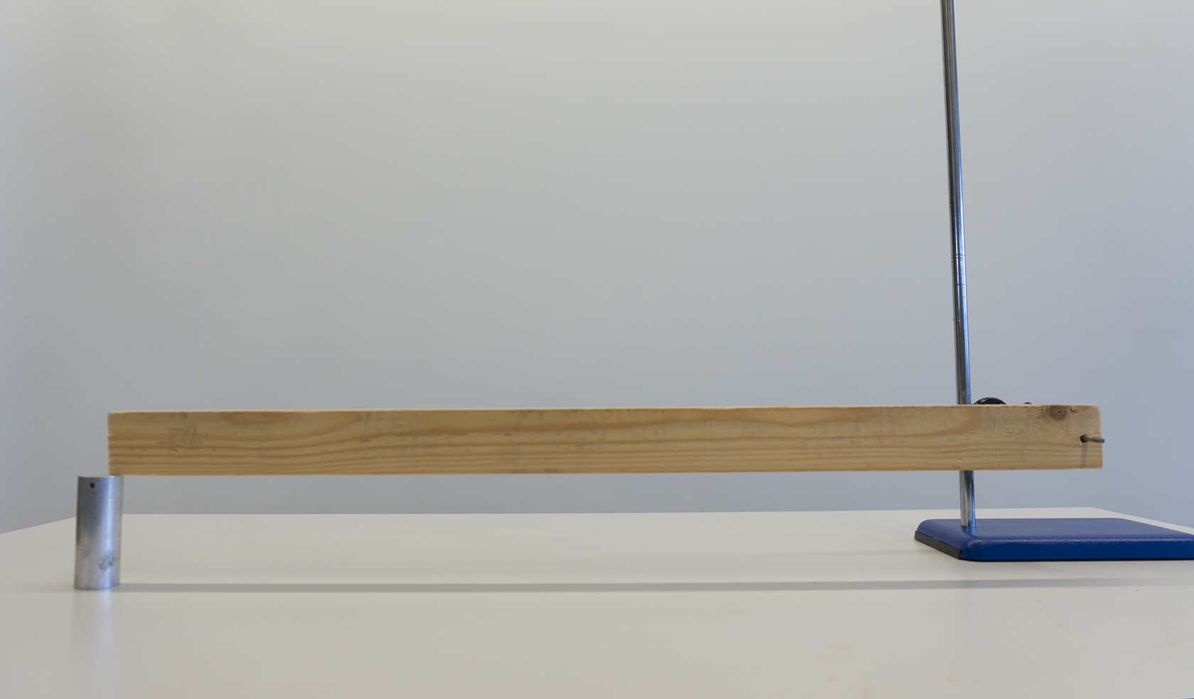
If the fulcrum is not aligned with the centre of mass, a single support point will not be able to negate the torque of weight. The bar in the photo below is supported with a laboratory stand rod on one end. The image below the photo shows the forces that have torque relative to the connection point. The bar stays balanced, because it is also supported from the other end. If we remove the support, the bar will rotate.
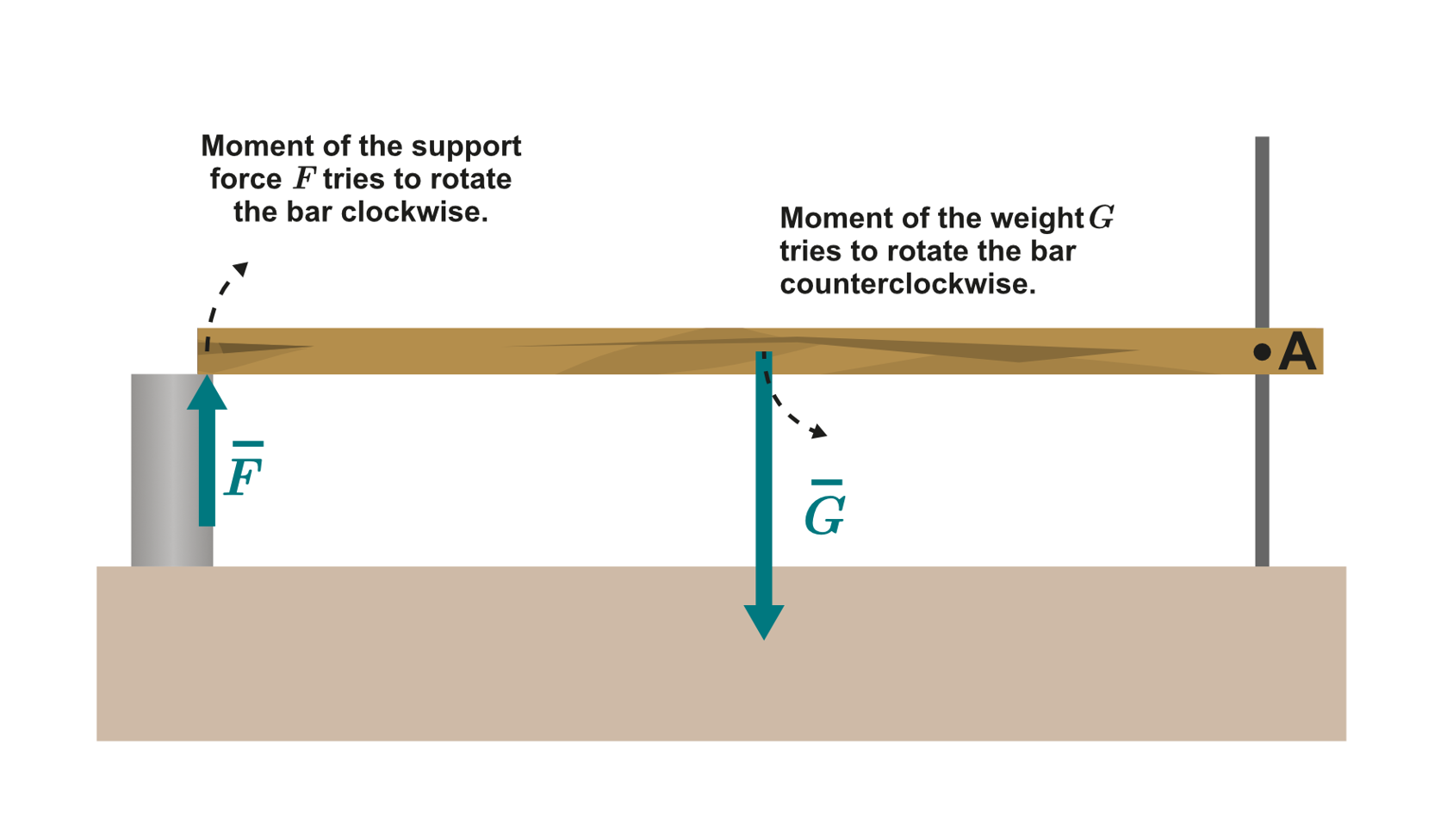
Let’s study the magnitude of torque in the situation we just described above, where the bar actually is a ruler. Weight is exerted on the ruler’s centre of mass, in the middle of the ruler. The support forces are acting on both ends of the ruler. If we want to negate the torque caused by the weight relative to axis A, we need another support force. The ruler will only remain balanced once the torques (moments of force) negate each other. If the torques do not negate each other, the ruler will rotate around axis A.
The magnitude of support force is measured with a force sensor and the distance between the force and moment axis A is read from the ruler’s scale. The accompanying video shows the measurement, and the results are plotted in an coordinate system.
The data below presents the measurement results in tabular form and as a graph. Function fits the plotted data points.
0.13 | 23.36 | 3.0 |
0.17 | 17.17 | 2.9 |
0.27 | 11.07 | 3.0 |
0.37 | 7.84 | 2.9 |
0.47 | 6.19 | 2.9 |
0.57 | 5.00 | 2.9 |
0.67 | 4.28 | 2.9 |
0.77 | 3.74 | 2.9 |
0.87 | 3.29 | 2.9 |
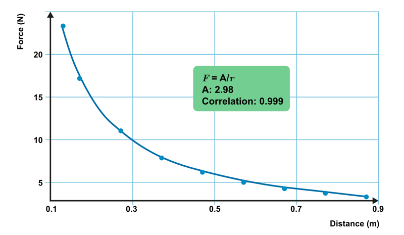
The magnitude of the required support force is inversely proportional to the distance. The further away from the moment axis the point of action of the force is, the less force we need to support the object. The product of force and distance that is required to keep the ruler stationary is constant. This quantity is the moment of force.
The prefix of the moment shows which direction the torque rotates an object in. The moments caused by weight and support force are equal but opposite, so their torques negate each other and the ruler remains stationary.
Note that multiplying distance with force can represent the work done or moment of force . Work is a scalar quantity whose unit is the joule, while moment is a vector quantity whose unit is the newton-metre. Remember that work and moment are different quantities that should not be mixed up.
The moment of a force is the product of the force and the perpendicular distance between the moment axis and the line of action of the force
The distance between the axis of rotation and the line of action of the force, , can also be referred to as the lever arm.
The unit for moment is the newton-metre:
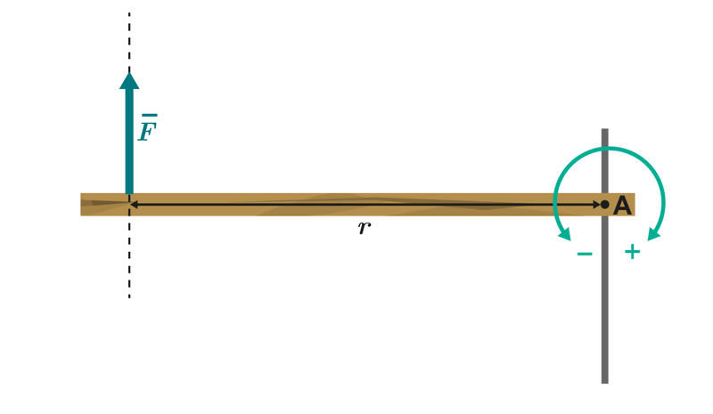
The diagram uses an arched arrow to show which direction of rotation is positive. The positive direction can also be written out in text.
The moment of force is calculated using the shortest distance between the line of action of the force and the moment axis. The distance is at its shortest when it is perpendicular to the force. In the situation with the ruler that we studied earlier, the force and its distance from the axis of rotation are perpendicular. If the force balancing the ruler is skewed, the shortest distance is not along the length of the ruler, but the perpendicular distance from the line of action to the axis.
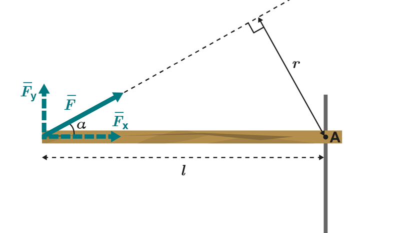
The expression that applies to the moment of force caused by force is
.
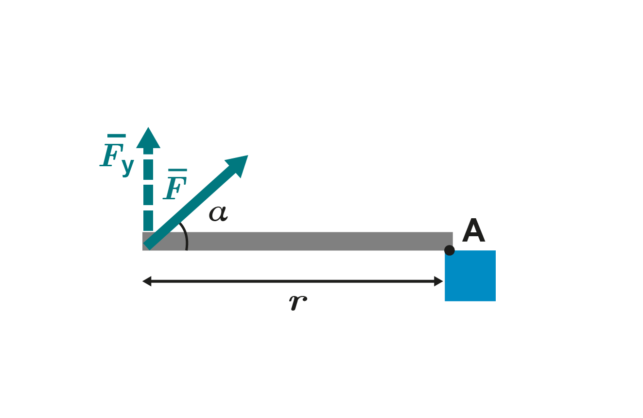
We can also think that the ruler is only held up by the force’s vertical component, . The component of force aligned with the ruler, , attempts to push the ruler towards the axis of rotation and does not rotate the ruler around the axis. The moment can therefore be expressed in another form.
The moments are the same regardless of how we form the expression. The distance, , is a part of a right triangle whose hypotenuse is . Using the angle α between the force and the ruler, we get the condition , so the moment is
.
The component written using the force is
.
If we place these two equations into the moment expression, we get
.
Splitting the force into components is often the easiest way to calculate the moment, but each situation should be judged separately. The known initial values determine the simplest way to calculate the moment.
1. The bar in the figure remains stationary when weight is placed on it as shown in the figure. What happens when the weight is moved to the right?
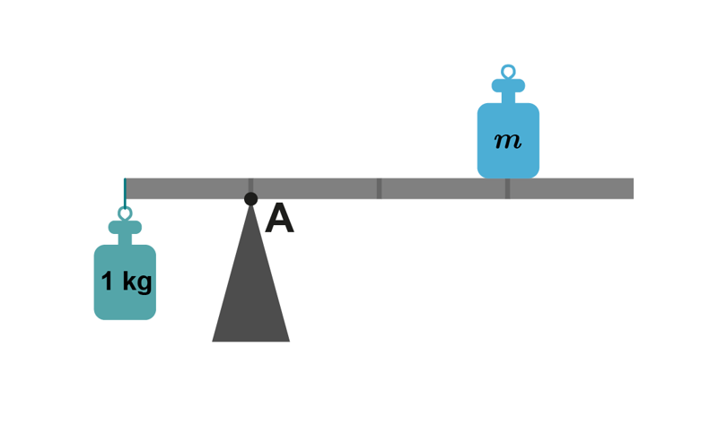
2. What is the mass of the weight if we assume that the bar’s mass is very small?
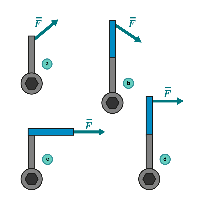
3. A stuck bolt is loosened with a wrench. What is the best way to loosen the bolt? The magnitude of force ( ) is the same in each situation.
A bar is kept balanced by supporting it from one end (Figure A). The support force is 76 N. The length of the bar is 135 cm.
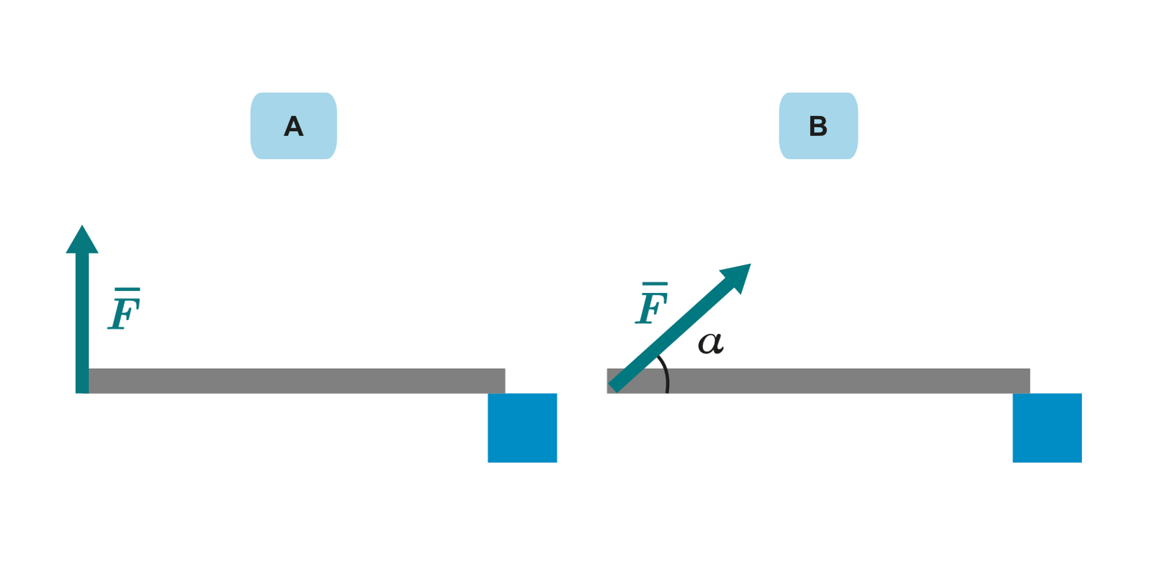
a. Calculate the moment caused by force :
The bar is balanced. The torque of weight is equal but opposite to the torque of force momentti. The torque of weight is 100 Nm.
b. To make the bar stay balanced, the torque caused by the support force must be equal to the torque of the weight. The torque of weight does not change, so the torque of the support force is also the same as in subsection ‘a’.
When the support point is moved towards the centre of the bar, the lever arm of the support force becomes shorter.
Because the torque does not change and the lever arm becomes shorter, the support force increases.
c. The supporting torque is the product of the force and the perpendicular distance.
Write the component using the force .
The range of values is 0–1. The smaller the angle, the smaller the value. Therefore, the smaller the angle , the greater the force . The support force is at its smallest when it is pointed directly upwards
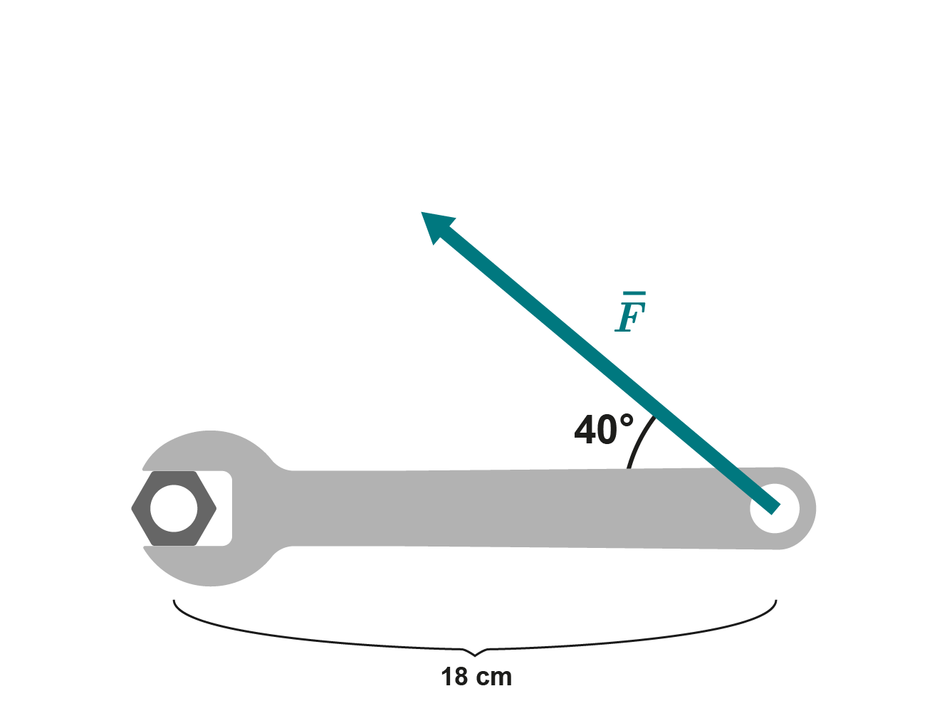
People sometimes have to work in difficult, cramped spaces. The moment required to loosen a certain bolt is 58 Nm.
An 18 cm wrench that can be tilted up to 40 degrees is being used.
Calculate the force that must be applied to the wrench to loosen the bolt.
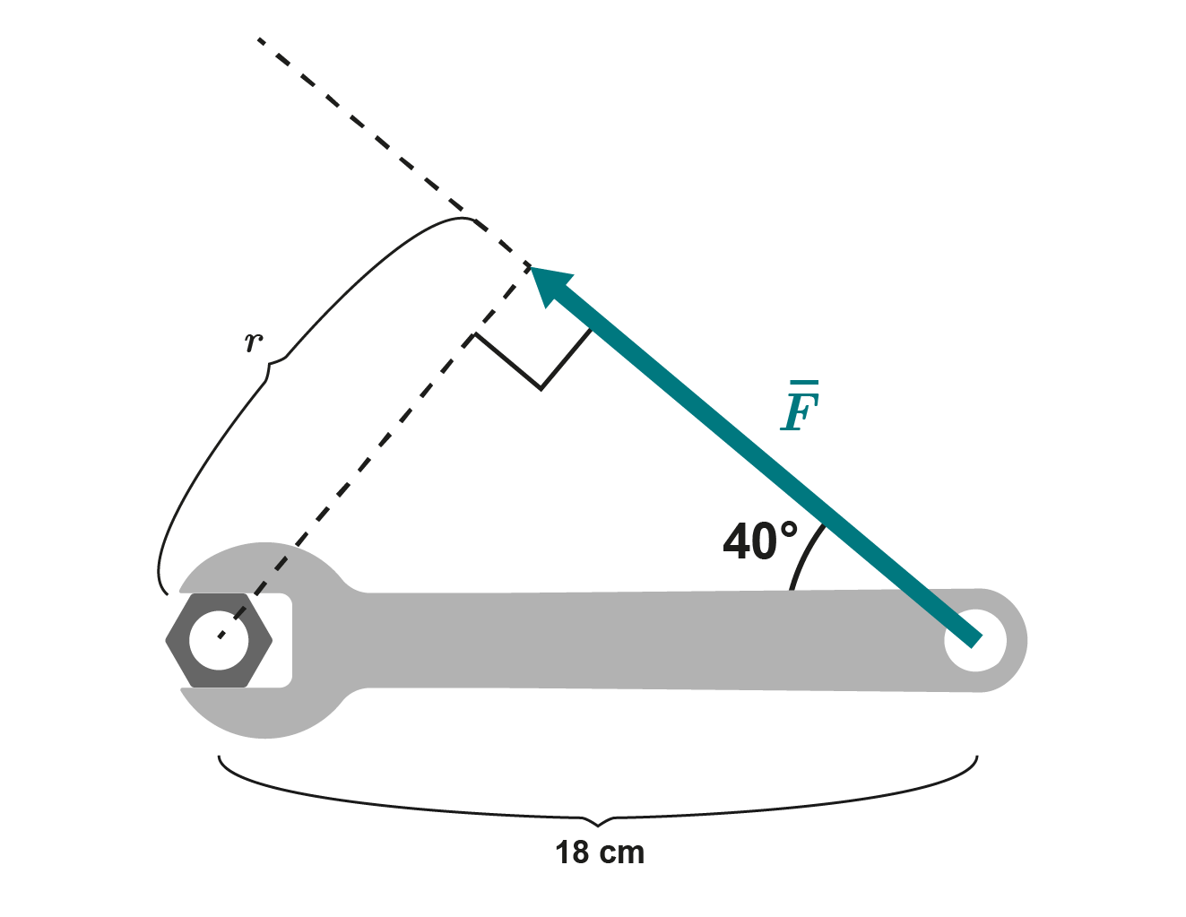
Let’s complement the figure to solve the moment. We can use the formed triangle to calculate the distance between the line of action of the force and the axis of rotation. In other words, we can calculate the length of the lever arm.
Using trigonometry, we get
We can now use the definition of moment and solve the required force:
The wrench needs to apply a force of about 500 N to the bolt.
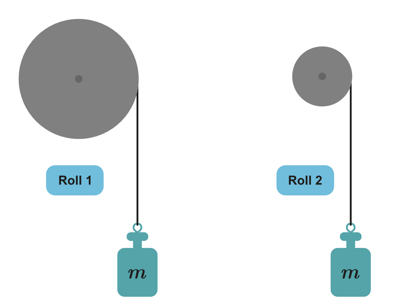
1. A weight is attached with a thread to a cylinder that can rotate around a central axis (see the figure below). Which cylinder is more difficult to keep stationary?
2. The diameter of cylinder 1 is twice as large as the diameter of cylinder 2. Which cylinder is more difficult to hold still when the mass of the weight hanging on cylinder 2 is doubled?
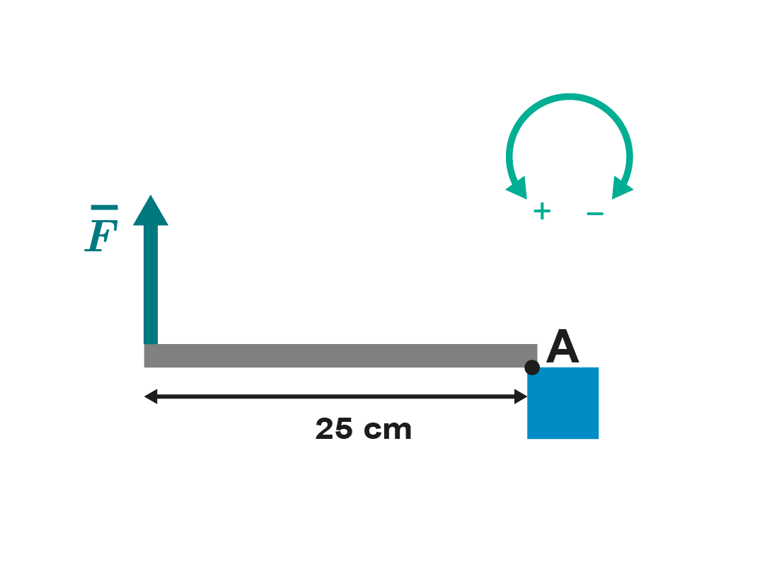
3. The amount of force applied ( ) is 10 N. What is the moment of force relative to the axis of rotation A? Give your answer with the accuracy of two significant digits. Note whether the moment is positive or negative.
Nm
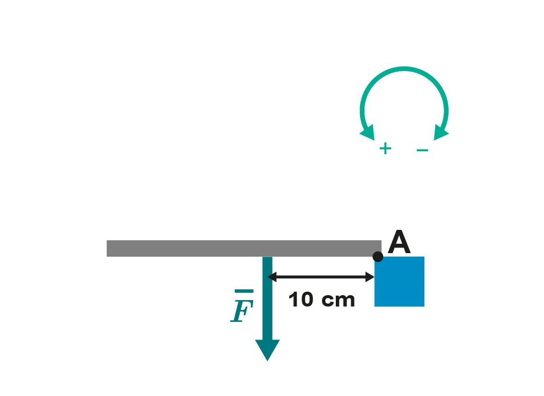
4. The amount of force applied () is 10 N. What is the moment of force relative to the axis of rotation A? Give your answer with the accuracy of two significant digits. Note whether the moment is positive or negative.
Nm
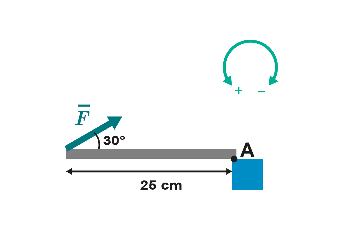
5. The amount of force applied () is 10 N. What is the moment of force relative to the axis of rotation A? Give your answer with the accuracy of two significant digits. Note whether the moment is positive or negative.
Nm
What would you like to do with the text? The text is processed by artificial intelligence, it is not checked or edited! The text may contain errors. Check the accuracy of the text against the original text in the textbook.
Choose the files you want to add. Supported formats are txt, html, htm, pdf, odt, odp, ods, xls, xlsx, ppt, pptx, pps, doc, docx, rtf, png, jpg, jpeg and gif.
| Name | |
|---|---|
| remove |
NB! Links must begin with: “http://”!
Opiq uses essential cookies to make our website work, to help keep you safe, to analyse user interaction and to improve user experience.
Cookie is a small file which is sent from users computer to the website server. It includes necessary information for the website to operate and includes information about the user and their preferences.
Most of the cookies are necessary for the operation of Opiq. It is possible to deny analytical cookies and in that case your usage data is not used to develop and improve Opiq services. Read more